Skip to content
Main Menu
PRODUCTS
Hardware
Software
SOLUTIONS
Tactical Radio Integration Kit
TRIK™
Tactical Multi-Enclave System
TMES
Tactical Data Link
TDL
Tactical Radio Integration Kit
TRIK™
Tactical Multi-Enclave System
TMES
Tactical Data Link
TDL
ABOUT
NEWSROOM
News
Blog
Events
Support
Contact
Main Menu
PRODUCTS
Hardware
Software
SOLUTIONS
Tactical Radio Integration Kit
TRIK™
Tactical Multi-Enclave System
TMES
Tactical Data Link
TDL
Tactical Radio Integration Kit
TRIK™
Tactical Multi-Enclave System
TMES
Tactical Data Link
TDL
ABOUT
NEWSROOM
News
Blog
Events
Support
Contact
Main Menu
Products
Hardware
Software
Solutions
Tactical Radio Integration Kit
TRIK™
Tactical Multi-Enclave System
TMES
Tactical Data Link
TDL
Tactical Radio Integration Kit
TRIK™
Tactical Multi-Enclave System
TMES
Tactical Data Link
TDL
About
Newsroom
News
Blog
Events
Support
Contact
Markets
Government
Transportation
Raven
Products
Hardware
About
Newsroom
News
Blog
Events
Support
Contact
Markets
Government
Transportation
Raven
Products
Hardware
About
Newsroom
News
Blog
Events
Support
Contact
/
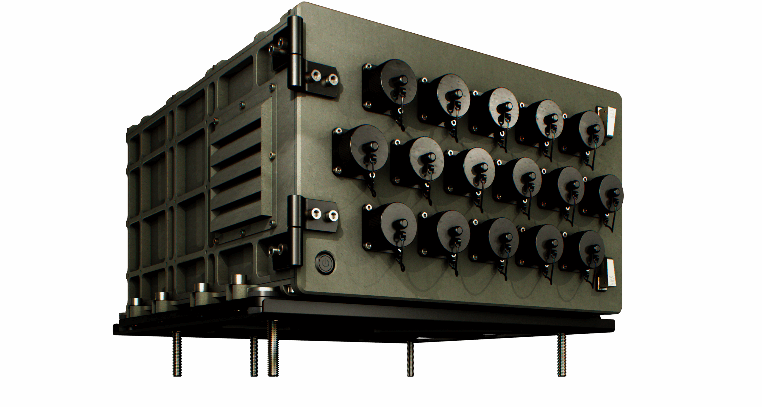
Chassis and Systems
Watch Video
Voyager 6 2.0 is a rugged chassis that powers and protects up to six standard Voyager form-factor modules.
Designed for a wide range of mounting capabilities, Voyager 6 is compatible with the Standardized A-Kit Vehicle Envelope (SAVE) space.
Voyager 6 2.0
Key Features
Supports up to six standard Voyager form-factor modules
28 VDC power input to MIL-STD-1275 (power supply protection) for vehicle installations
Compatible with Standardized A-Kit / Vehicle Envelope (SAVE) specifications
Chassis can be removed from the shock-mounted tray
Optional external PSU (200 W & 600 W) available for use in desktop environments
Download Brochure
Contact Us
Scroll to Top